| This article has been published [fromdate] |
| [readtime] |
I/O Addresses
Computer electronics can be interfaced to a range of devices. Data will flow through the electronic circuitry to and from these devices as 1s and 0s.
Each input & output circuit is identified number — an I/O address. Typical PCs have tens of thousands of I/O address but not all are used. A single device may use a number of I/O addresses depending on its complexity.
Parallel & serial
A single data transfer between a computer and another device is usually called a word. Depending on the design, a word may be 8 bits, 16 bits or 32 bits in size. There are two ways to transfer a word of data: parallel or serial.
Note: the PC was originally built around a 16-bit processor, so programmers often talk about a "word" as 16 bits. Hardware designers, however, use "word" to mean the number of bits in a single data transfer.
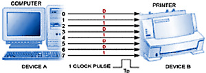
In parallel data transfer, the connection has a wire for each data bit and ground wire(s) to provide a reference voltage. Thus the entire word is transferred in one instant. This is fast but electrical effect limit the effectiveness of parallel connections over long distances.

Serial data transfer uses a single data wire (and single ground wire). The data is sent one-bit-at-a-time at regular intervals (clock pulses). Serial transfer is slower but more effective over longer distances, and requires fewer wires.

There are two types of serial transfer: synchronous (where data words are sent continuously and the clock pulse accompanies the data signal) and asynchronous (where data words are sent at irregular intervals).
Most data transfers inside a computer are carried out in parallel for speed; many peripherals use serial transfer.
Controlling I/O devices
Programmed I/O
Most devices use programmed I/O: this allows the processor to use specific I/O address(es) to read & write data and other I/O address(es) to send control signals to the device.
Polling
The processor may check the status of an I/O device by polling it. This is a regular check asking the device if it needs to send data to the processor.
However, because devices rarely need to send data, polling is very inefficient.
Interrupts
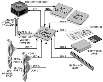
Because polling is inefficient, most processors allow devices to interrupt the processor using a special interrupt (INT) signal wire.
When a device triggers an interrupt the processor temporarily stops what it is doing, runs a service routine program and signals an interrupt acknowledge (INTA). When suspending a task, details are temporarily stored in the system stack storage area. These details are retrieved when the servicing has been completed and the processor carries on as before.
Note: these interrupt signals may be masked (switched off) by a program as required. However, there is a special non-maskable interrupt (NMI) wire used for 'emergencies' such as memory errors.
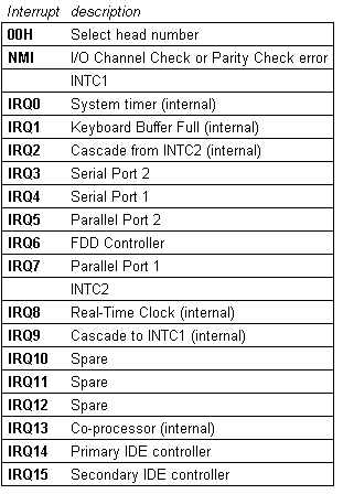
PCs use a Programmable Interrupt Controller (PIC) chip to create a number of IRQ (interrupt request) wires: thus a device with a higher priority interrupt can interrupt the service routine of a lower priority one.
A single PIC would provide 8 wires (IRQ0 to IRQ7) but most PCs use a cascaded system with a second PIC giving IRQ0 to IRQ15. IRQ0 is the highest priority.


I/O addresses
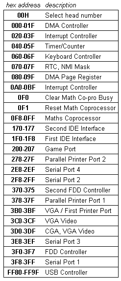
Devices may use any I/O addresses but design conventions have led to particular addresses being set aside for particular devices.
I/O addresses are always given in hexadecimal, a shorthand form of binary. To identify them from normal decimal numbers, 'hex' numbers often start with 0x or $ or end with H.

SOURCE | LINK (talktoanit.com) | LANGUAGE | ENGLISH |

