To totally unlock this section you need to Log-in
Login
A Local Area Network (LAN) was originally defined as a network of computers located within the same area. Today, Local Area Networks are defined as a single broadcast domain. This means that if a user broadcasts information on his/her LAN, the broadcast will be received by every other user on the LAN.
Broadcasts are prevented from leaving a LAN by using a router. The disadvantage of this method is routers usually take more time to process incoming data compared to a bridge or a switch. More importantly, the formation of broadcast domains depends on the physical connection of the devices in the network. Virtual Local Area Networks (VLAN's) were developed as an alternative solution to using routers to contain broadcast traffic.
What are VLAN's?
In a traditional LAN, workstations are connected to each other by means of a hub or a repeater. These devices propagate any incoming data throughout the network. However, if two people attempt to send information at the same time, a collision will occur and all the transmitted data will be lost. Once the collision has occurred, it will continue to be propagated throughout the network by hubs and repeaters.
The original information will therefore need to be resent after waiting for the collision to be resolved, thereby incurring a significant wastage of time and resources. To prevent collisions from traveling through all the workstations in the network, a bridge or a switch can be used. These devices will not forward collisions, but will allow broadcasts (to every user in the network) and multicasts (to a pre-specified group of users) to pass through. A router may be used to prevent broadcasts and multicasts from traveling through the network.
The workstations, hubs, and repeaters together form a LAN segment. A LAN segment is also known as a collision domain since collisions remain within the segment. The area within which broadcasts and multicasts are confined is called a broadcast domain or LAN. Thus a LAN can consist of one or more LAN segments. Defining broadcast and collision domains in a LAN depends on how the workstations, hubs, switches, and routers are physically connected together. This means that everyone on a LAN must be located in the same area (see Figure 1).
VLAN's allow a network manager to logically segment a LAN into different broadcast domains (see Figure 2). Since this is a logical segmentation and not a physical one, workstations do not have to be physically located together. Users on different floors of the same building, or even in different buildings can now belong to the same LAN.
VLAN's also allow broadcast domains to be defined without using routers. Bridging software is used instead to define which workstations are to be included in the broadcast domain. Routers would only have to be used to communicate between two VLAN's.
Why use VLAN's?
VLAN's offer a number of advantages over traditional LAN's. They are:
1) Performance
In networks where traffic consists of a high percentage of broadcasts and multicasts, VLAN's can reduce the need to send such traffic to unnecessary destinations. For example, in a broadcast domain consisting of 10 users, if the broadcast traffic is intended only for 5 of the users, then placing those 5 users on a separate VLAN can reduce traffic.
Compared to switches, routers require more processing of incoming traffic. As the volume of traffic passing through the routers increases, so does the latency in the routers, which results in reduced performance. The use of VLAN's reduces the number of routers needed, since VLAN's create broadcast domains using switches instead of routers.
2) Formation of Virtual Workgroups
Nowadays, it is common to find cross-functional product development teams with members from different departments such as marketing, sales, accounting, and research. These workgroups are usually formed for a short period of time. During this period, communication between members of the workgroup will be high. To contain broadcasts and multicasts within the workgroup, a VLAN can be set up for them. With VLAN's it is easier to place members of a workgroup together. Without VLAN's, the only way this would be possible is to physically move all the members of the workgroup closer together.
However, virtual workgroups do not come without problems. Consider the situation where one user of the workgroup is on the fourth floor of a building, and the other workgroup members are on the second floor. Resources such as a printer would be located on the second floor, which would be inconvenient for the lone fourth floor user.
Another problem with setting up virtual workgroups is the implementation of centralized server farms, which are essentially collections of servers and major resources for operating a network at a central location. The advantages here are numerous, since it is more efficient and cost-effective to provide better security, uninterrupted power supply, consolidated backup, and a proper operating environment in a single area than if the major resources were scattered in a building.
Centralized server farms can cause problems when setting up virtual workgroups if servers cannot be placed on more than one VLAN. In such a case, the server would be placed on a single VLAN and all other VLAN's trying to access the server would have to go through a router; this can reduce performance.
3) Simplified Administration
Seventy percent of network costs are a result of adds, moves, and changes of users in the network [ Buerger]. Every time a user is moved in a LAN, recabling, new station addressing, and reconfiguration of hubs and routers becomes necessary. Some of these tasks can be simplified with the use of VLAN's. If a user is moved within a VLAN, reconfiguration of routers is unnecessary. In addition, depending on the type of VLAN, other administrative work can be reduced or eliminated. However the full power of VLAN's will only really be felt when good management tools are created which can allow network managers to drag and drop users into different VLAN's or to set up aliases.
Despite this saving, VLAN's add a layer of administrative complexity, since it now becomes necessary to manage virtual workgroups.
4) Reduced Cost
VLAN's can be used to create broadcast domains which eliminate the need for expensive routers.
5) Security
Periodically, sensitive data may be broadcast on a network. In such cases, placing only those users who can have access to that data on a VLAN can reduce the chances of an outsider gaining access to the data. VLAN's can also be used to control broadcast domains, set up firewalls, restrict access, and inform the network manager of an intrusion.
How VLAN's work
When a LAN bridge receives data from a workstation, it tags the data with a VLAN identifier indicating the VLAN from which the data came. This is called explicit tagging. It is also possible to determine to which VLAN the data received belongs using implicit tagging. In implicit tagging the data is not tagged, but the VLAN from which the data came is determined based on other information like the port on which the data arrived.
Tagging can be based on the port from which it came, the source Media Access Control (MAC) field, the source network address, or some other field or combination of fields. VLAN's are classified based on the method used. To be able to do the tagging of data using any of the methods, the bridge would have to keep an updated database containing a mapping between VLAN's and whichever field is used for tagging. For example, if tagging is by port, the database should indicate which ports belong to which VLAN. This database is called a filtering database.
Bridges would have to be able to maintain this database and also to make sure that all the bridges on the LAN have the same information in each of their databases. The bridge determines where the data is to go next based on normal LAN operations. Once the bridge determines where the data is to go, it now needs to determine whether the VLAN identifier should be added to the data and sent. If the data is to go to a device that knows about VLAN implementation (VLAN-aware), the VLAN identifier is added to the data. If it is to go to a device that has no knowledge of VLAN implementation (VLAN-unaware), the bridge sends the data without the VLAN identifier.
In order to understand how VLAN's work, we need to look at the types of VLAN's, the types of connections between devices on VLAN's, the filtering database which is used to send traffic to the correct VLAN, and tagging, a process used to identify the VLAN originating the data.
VLAN Standard: IEEE 802.1Q Draft Standard
There has been a recent move towards building a set of standards for VLAN products. The Institute of Electrical and Electronic Engineers (IEEE) is currently working on a draft standard 802.1Q for VLAN's. Up to this point, products have been proprietary, implying that anyone wanting to install VLAN's would have to purchase all products from the same vendor. Once the standards have been written and vendors create products based on these standards, users will no longer be confined to purchasing products from a single vendor. The major vendors have supported these standards and are planning on releasing products based on them. It is anticipated that these standards will be ratified later this year.
Types of VLAN's
VLAN membership can be classified by port, MAC address, and protocol type.
Layer 1 VLAN: Membership by Port
Membership in a VLAN can be defined based on the ports that belong to the VLAN. For example, in a bridge with four ports, ports 1, 2, and 4 belong to VLAN 1 and port 3 belongs to VLAN 2 (see Figure 3).
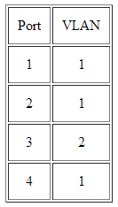
The main disadvantage of this method is that it does not allow for user mobility. If a user moves to a different location away from the assigned bridge, the network manager must reconfigure the VLAN.
Layer 2 VLAN: Membership by MAC Address
Here, membership in a VLAN is based on the MAC address of the workstation. The switch tracks the MAC addresses which belong to each VLAN (see Figure 4). Since MAC addresses form a part of the workstation's network interface card, when a workstation is moved, no reconfiguration is needed to allow the workstation to remain in the same VLAN. This is unlike Layer 1 VLAN's where membership tables must be reconfigured.
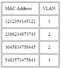
The main problem with this method is that VLAN membership must be assigned initially. In networks with thousands of users, this is no easy task. Also, in environments where notebook PC's are used, the MAC address is associated with the docking station and not with the notebook PC. Consequently, when a notebook PC is moved to a different docking station, its VLAN membership must be reconfigured.
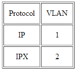
Layer 2 VLAN: Membership by Protocol Type
VLAN membership for Layer 2 VLAN's can also be based on the protocol type field found in the Layer 2 header (see Figure 5).
Layer 3 VLAN: Membership by IP Subnet Address
Membership is based on the Layer 3 header. The network IP subnet address can be used to classify VLAN membership (see Figure 6).
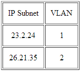
Although VLAN membership is based on Layer 3 information, this has nothing to do with network routing and should not be confused with router functions. In this method, IP addresses are used only as a mapping to determine membership in VLAN's. No other processing of IP addresses is done.
In Layer 3 VLAN's, users can move their workstations without reconfiguring their network addresses. The only problem is that it generally takes longer to forward packets using Layer 3 information than using MAC addresses.
Higher Layer VLAN's
It is also possible to define VLAN membership based on applications or service, or any combination thereof. For example, file transfer protocol (FTP) applications can be executed on one VLAN and telnet applications on another VLAN.
The 802.1Q draft standard defines Layer 1 and Layer 2 VLAN's only. Protocol type based VLAN's and higher layer VLAN's have been allowed for, but are not defined in this standard. As a result, these VLAN's will remain proprietary.
Types of Connections
Devices on a VLAN can be connected in three ways based on whether the connected devices are VLAN-aware or VLAN-unaware. Recall that a VLAN-aware device is one which understands VLAN memberships (i.e. which users belong to a VLAN) and VLAN formats.
Trunk Link
A Trunk Link, or 'Trunk' is a port configured to carry packets for any VLAN. These type of ports are usually found in connections between switches. These links require the ability to carry packets from all available VLANs because VLANs span over multiple switches.
The diagram below shows multiple switches connected throughout a network and the Trunk Links are marked in purple colour to help you identify them:
As you can see in our diagram, our switches connect to the network backbone via the Trunk Links. This allows all VLANs created in our network to propagate throughout the whole network. Now in the unlikely event of Trunk Link failure on one of our switches, the devices connected to that switch's ports would be isolated from the rest of the network, allowing only ports on that switch, belonging to the same VLAN, to communicate with each other.
So now that we have an idea of what Trunk Links are and their purpose, let's take a look at an actual switch to identify a possible Trunk Link:
The Gigabit ports are usually configured as Trunk Links, connecting the switch to the network backbone at the speed of 1 Gigabit, while the Access Link ports connect at 100Mbits.
In addition, we should note that for a port or link to operate as a Trunk Link, it is imperative that it runs at speeds of 100Mbit or greater. A port running at speeds of 10Mbit's cannot operate as a Trunk Link and this is logical because a Trunk Link is always used to connect to the network backbone, which must operate at speeds greater than most Access Links.
All the devices connected to a trunk link, including workstations, must be VLAN-aware. All frames on a trunk link must have a special header attached. These special frames are called tagged frames (see Figure 7).
Access Link
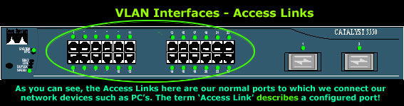
An access link connects a VLAN-unaware device to the port of a VLAN-aware bridge. All frames on access links must be implicitly tagged (untagged) (see Figure 8). The VLAN-unaware device can be a LAN segment with VLAN-unaware workstations or it can be a number of LAN segments containing VLAN-unaware devices (legacy LAN).
Access Links are the most common type of links on any VLAN switch. All network hosts connect to the switch's Access Links in order to gain access to the local network. These links are your ordinary ports found on every switch, but configured in a special way, so you are able to plug a computer into them and access your network.
Here's a picture of a Cisco Catalyst 3550 series switch, with it's Access Links (ports) marked in the green circle:
Frame Processing
A bridge on receiving data determines to which VLAN the data belongs either by implicit or explicit tagging. In explicit tagging a tag header is added to the data. The bridge also keeps track of VLAN members in a filtering database which it uses to determine where the data is to be sent. Following is an explanation of the contents of the filtering database and the format and purpose of the tag header [802.1Q].
Filtering Database
Membership information for a VLAN is stored in a filtering database. The filtering database consists of the following types of entries:
Static Entries: static information is added, modified, and deleted by management only. Entries are not automatically removed after some time (ageing), but must be explicitly removed by management. There are two types of static entries:
- Static Filtering Entries: which specify for every port whether frames to be sent to a specific MAC address or group address and on a specific VLAN should be forwarded or discarded, or should follow the dynamic entry.
- Static Registration Entries: which specify whether frames to be sent to a specific VLAN are to be tagged or untagged and which ports are registered for that VLAN.
Dynamic Entries: dynamic entries are learned by the bridge and cannot be created or updated by management. The learning process observes the port from which a frame, with a given source address and VLAN ID (VID), is received, and updates the filtering database. The entry is updated only if all the following three conditions are satisfied:
- this port allows learning;
- the source address is a workstation address and not a group address;
- there is space available in the database.
Entries are removed from the database by the ageing out process where, after a certain amount of time specified by management (10 sec --- 1000000 sec), entries allow automatic reconfiguration of the filtering database if the topology of the network changes. There are three types of dynamic entries:
- Dynamic Filtering Entries: which specify whether frames to be sent to a specific MAC address and on a certain VLAN should be forwarded or discarded.
- Group Registration Entries: which indicate for each port whether frames to be sent to a group MAC address and on a certain VLAN should be filtered or discarded. These entries are added and deleted using Group Multicast Registration Protocol (GMRP). This allows multicasts to be sent on a single VLAN without affecting other VLAN's.
- Dynamic Registration Entries: which specify which ports are registered for a specific VLAN. Entries are added and deleted using GARP VLAN Registration Protocol (GVRP), where GARP is the Generic Attribute Registration Protocol.
GVRP is used not only to update dynamic registration entries, but also to communicate the information to other VLAN-aware bridges.
In order for VLAN's to forward information to the correct destination, all the bridges in the VLAN should contain the same information in their respective filtering databases. GVRP allows both VLAN-aware workstations and bridges to issue and revoke VLAN memberships. VLAN-aware bridges register and propagate VLAN membership to all ports that are a part of the active topology of the VLAN. The active topology of a network is determined when the bridges are turned on or when a change in the state of the current topology is perceived.
The active topology is determined using a spanning tree algorithm which prevents the formation of loops in the network by disabling ports. Once an active topology for the network (which may contain several VLAN's) is obtained, the bridges determine an active topology for each VLAN. This may result in a different topology for each VLAN or a common one for several VLAN's. In either case, the VLAN topology will be a subset of the active topology of the network (see Figure 10).
VLAN Tagging
VLAN Trunking Protocol (VTP) is a Cisco proprietary protocol that propagates the definition of Virtual Local Area Networks (VLAN) on the whole local area network. To do this, VTP carries VLAN information to all the switches in a VTP domain. VTP advertisements can be sent over ISL, 802.1Q, IEEE 802.10 and LANE trunks. VTP is available on most of the Cisco Catalyst Family products. Using VTP, each Catalyst Family Switch advertises the following on its trunk ports:
- Management domain
- Configuration revision number
- Known VLANs and their specific parameters
- There are three versions of VTP, namely version 1, version 2, version 3.
VLAN Tagging, also known as Frame Tagging, is a method developed by Cisco to help identify packets travelling through trunk links. When an Ethernet frame traverses a trunk link, a special VLAN tag is added to the frame and sent across the trunk link.
Here we see two 3500 series Catalyst switches and one Cisco 3745 router connected via the Trunk Links. The Trunk Links allow frames from all VLANs to travel throughout the network backbone and reach their destination regardless of the VLAN the frame belongs to. On the other side, the workstations are connected directly to Access Links (ports configured for one VLAN membership only), gaining access to the resources required by VLAN's members.
Again, when we call a port 'Access Link' or 'Trunk Link', we are describing it based on the way it has been configured. This is because a port can be configured as an Access Link or Trunk Link (in this last case where it's 100Mbits or faster).
When frames are sent across the network, there needs to be a way of indicating to which VLAN the frame belongs, so that the bridge will forward the frames only to those ports that belong to that VLAN, instead of to all output ports as would normally have been done. This information is added to the frame in the form of a tag header. In addition, the tag header:
- allows user priority information to be specified;
- allows source routing control information to be specified;
- indicates the format of MAC addresses.
Frames in which a tag header has been added are called tagged frames. Tagged frames convey the VLAN information across the network.
The tagged frames that are sent across hybrid and trunk links contain a tag header. There are two formats of the tag header:
Ethernet Frame Tag Header: The ethernet frame tag header (see Figure 11) consists of a tag protocol identifier (TPID) and tag control information (TCI).

Token Ring and Fiber Distributed Data Interface (FDDI) tag header: The tag headers for both token ring and FDDI networks consist of a SNAP-encoded TPID and TCI.
TPID is the tag protocol identifier which indicates that a tag header is following and TCI (see Figure 13) contains the user priority, canonical format indicator (CFI), and the VLAN ID.
User priority is a 3 bit field which allows priority information to be encoded in the frame. Eight levels of priority are allowed, where zero is the lowest priority and seven is the highest priority. How this field is used is described in the supplement 802.1p.
The CFI bit is used to indicate that all MAC addresses present in the MAC data field are in canonical format. This field is interpreted differently depending on whether it is an ethernet-encoded tag header or a SNAP-encoded tag header. In SNAP-encoded TPID the field indicates the presence or absence of the canonical format of addresses. In ethernet-encoded TPID, it indicates the presence of the Source-Routing Information (RIF) field after the length field. The RIF field indicates routing on ethernet frames.
The VID field is used to uniquely identify the VLAN to which the frame belongs. There can be a maximum of (2 12 - 1) VLAN's.
Zero is used to indicate no VLAN ID, but that user priority information is present. This allows priority to be encoded in non-priority LAN's.
Interswitch Link (ISL)
ISL is a Cisco propriety protocol used for FastEthernet and Gigabit Ethernet links only. The protocol can be used in various equipments such as switch ports, router interfaces, server interface cards to create a trunk to a server and much more.
Being a propriety protocol, ISL is available and supported naturally on Cisco products only:) You may also be interested in knowing that ISL is what we call, an 'external tagging process'. This means that the protocol does not alter the Ethernet frame as shown above in our previous diagram - placing the VLAN Tag inside the Ethernet frame, but encapsulating the Ethernet frame with a new 26 byte ISL header and adding an additional 4 byte frame check sequence (FCS) field at the end of frame, as illustrated below:
Despite this extra overhead, ISL is capable of supporting up to 1000 VLANs and does not introduce any delays in data transfers between Trunk Links.
In the above diagram we can see an ISL frame encapsulating an Ethernet II frame. This is the actual frame that runs through a trunk link between two Cisco devices when configured to use ISL as their trunk tagging protocol.
The encapsulation method mentioned above also happens to be the reason why only ISL-aware devices are able to read it, and because of the addition of an ISL header and FCS field, the frame can end up being 1548 bytes long! For those who can't remember, Ethernet's maximum frame size is 1518 bytes, making an ISL frame of 1548 bytes, what we call a 'giant' or 'jumbo' frame!
Lastly, ISL uses Per VLAN Spanning Tree (PVST) which runs one instance of the Spanning Tree Protocol (STP) per VLAN. This method allows us to optimise the root switch placement for each available VLAN while supporting neat features such as VLAN load balancing between multiple trunks.
IEEE 802.1Q
The 802.1q standard was created by the IEEE group to address the problem breaking large networks into smaller and manageable ones through the use of VLANs. The 802.1q standard is of course an alternative to Cisco's ISL, and one that all vendors implement on their network equipment to ensure compatibility and seamless integration with the existing network infrastructure.
As with all 'open standards' the IEEE 802.1q tagging method is by far the most popular and commonly used even in Cisco oriented network installations mainly for compatability with other equipment and future upgrades that might tend towards different vendors.
In addition to the compatability issue, there are several more reasons for which most engineers prefer this method of tagging. These include:
- Support of up to 4096 VLANs
- Insertion of a 4-byte VLAN tag with no encapsulation
- Smaller final frame sizes when compared with ISL
Amazingly enough, the 802.1q tagging method supports a whopping 4096 VLANs (as opposed to 1000 VLANs ISL supports), a large amount indeed which is merely impossible to deplet in your local area network.
The 4-byte tag we mentioned is inserted within the existing Ethernet frame, right after the Source MAC Address as illustrated in the diagram below:
Because of the extra 4-byte tag, the minimum Ethernet II frame size increases from 64 bytes to 68 bytes, while the maximum Ethernet II frame size now becomes 1522 bytes. If you require more information on the tag's fields, visit our protocol page where further details are given.
As you may have already concluded yourself, the maximum Ethernet frame is considerably smaller in size (by 26 bytes) when using the IEEE 802.1q tagging method rather than ISL.
This difference in size might also be interpreted by many that the IEEE 802.1q tagging method is much faster than ISL, but this is not true. In fact, Cisco recommends you use ISL tagging when in a Cisco native environment, but as outlined earlier, most network engineers and administrators believe that the IEEE 802.1q approach is much safer, ensuring maximum compatability.
And because not everything in this world is perfect, no matter how good the 802.1q tagging protocol might seem, it does come with its restrictions:
In a Cisco powered network, the switch maintains one instance of the Spanning Tree Protocol (STP) per VLAN. This means that if you have 10 VLANs in your network, there will also be 10 instances of STP running amongst the switches. In the case of non-Cisco switches, then only 1 instance of STP is maintained for all VLANs, which is certainly not something a network administrator would want.
It is imperative that the VLAN for an IEEE 802.1q trunk is the same for both ends of the trunk link, otherwise network loops are likely to occur.
Cisco always advises that disabling a STP instance on one 802.1q VLAN trunk without disabling it on the rest of the available VLANs, is not a good idea because network loops might be created. It's best to either disable or enable STP on all VLANs.
LAN EMULATION (LANE)
LANE is a protocol that allows existing networked applications and protocols to run over an ATM backbone. LANs are connectionless while ATM is a connection-oriented technology. LANE provides a means for ATM hardware and networks to communicate with existing Ethernet and Token Ring networks. LANE works at the MAC (layer 2) networking layer of the OSI model and therefore supports both bridging and routing.
The main objective of LAN emulation is to allow existing applications to access the ATM network by way of MAC drivers as if they were running over traditional LAN's. Standard interfaces for MAC device drivers include NDIS and ODI.
LAN Emulation was introduced to solve the need of creating VLANs over WAN links, allowing network managers to define workgroups based on logical function, rather than physical location. With this new technology (it's actually been around since 1995), we are now able to create VLANs between remote offices, regardless of their location and distance.
LANE is not very common and you will most probably never see it implemented in small to mid-sized networks, however, this is no reason to ignore it.
LANE has been supported by Cisco since 1995 and Cisco's ISO release 11.0. When implemented between two point-to-point links, the WAN network becomes totally transparent to the end users:
Every LAN or native ATM host, like the switch or router shown in the diagram, connects to the ATM network via a special software interface called 'LAN Emulation Client'. The LANE Client works with the LAN Emulation Server (LES) to handle all messages and packets flowing through the network, ensuring that the end clients are not aware of the WAN network infrastructure and therefore making it transparent.
The LANE specification defines a LAN Emulation Configuration Server (LECS), a service running inside an ATM switch or a physical server connected to the ATM switch, that resides within the ATM network and allows network administrators to control which LANs are combined to form VLANs.
The LAN Emulation Server with the help of the LANE Client, maps MAC addresses to ATM addresses, emulating Layer 2 protocols (DataLink layer) and transporting higher layer protocols such as TCP/IP, IPX/SPX without modification.
802.10 (FDDI)
Tagging VLAN frames on Fiber Distributed Data Interface (FDDI) networks is quite common in large scale networks. This implementation is usually found on Cisco's high-end switch models such as the Catalyst 5000 series where special modules are installed inside the switches, connecting them to an FDDI backbone. This backbone interconnects all major network switches, providing a fully redundant network.
The various modules available for the Cisco Catalyst switches allow the integration of Ethernet into the FDDI network. When intalling the appropriate switch modules and with the use of the 802.10 SAID field, a mapping between the Ethernet VLAN and 802.10 network is created, and as such, all Ethernet VLANs are able to run over the FDDI network.
The diagram above shows two Catalyst switches connected to a FDDI backbone. The links between the switches and the backbone can either be Access type links (meaning one VLAN passes through them) or Trunk links (all VLANs are able to pass through them). At both ends, the switches have an Ethernet port belonging to VLAN 6, and to 'connect' these ports we map each switch's Ethernet module with its FDDI module.
Lastly, the special FDDI modules mentioned above support both single VLANs (non-trunk) and multiple VLANs (trunk).
To provide further detail, the diagram below shows the IEEE 802.10 frame, along with the SAID field in which the VLAN ID is inserted, allowing the frame to transit trunk links as described:
On the Cisco switch in the previous diagram must process the Ethernet II frame and convert it before placing it on the IEEE 802.10 backbone or trunk.
During this stage, the original Ethernet II frame is converted to an Ethernet SNAP frame and then finally to an IEEE 802.10 frame. This conversion is required to maintain compatability and reliability between the two different topologies. The most important bit to remember here is the SAID field and its purpose.
 |  |